

Different projects demand different fire testing standards and often clients ask us about the differences of these tests, we chose four common standard tests on the spread of flame which were reviewed with the aim of illustrating how flame spreading behavior of materials and components can be tested. Those four standard tests are:
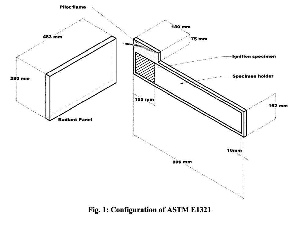
ASTM E1321-97a
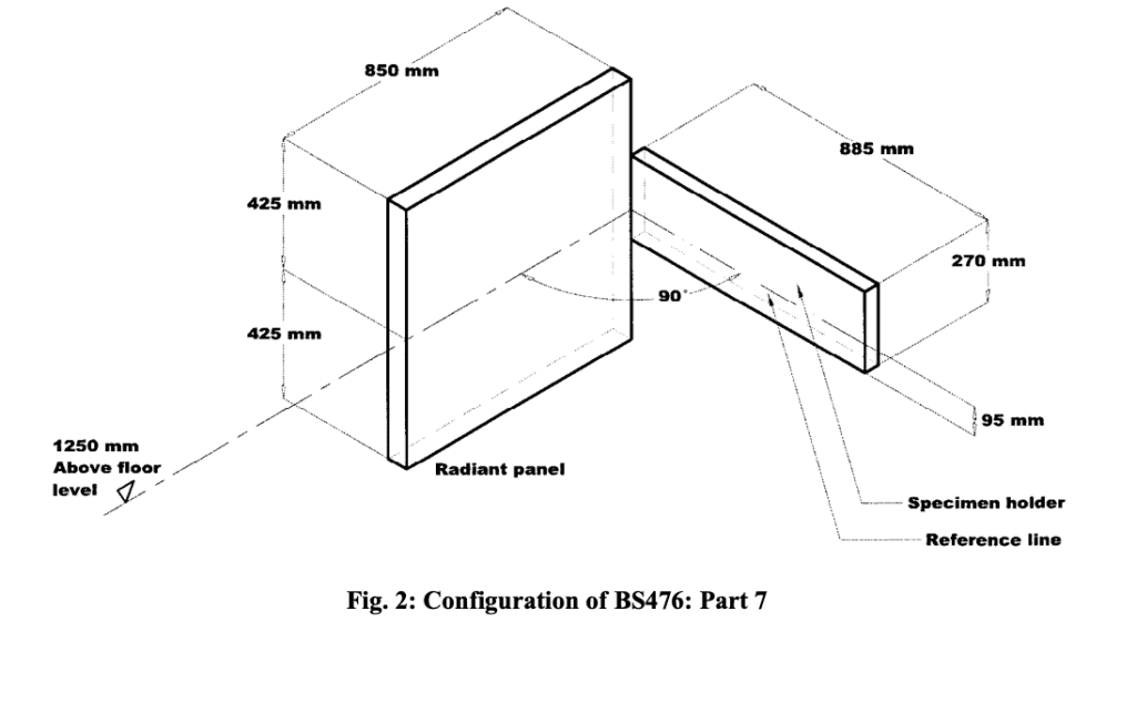
BS476: Part 7: 1997
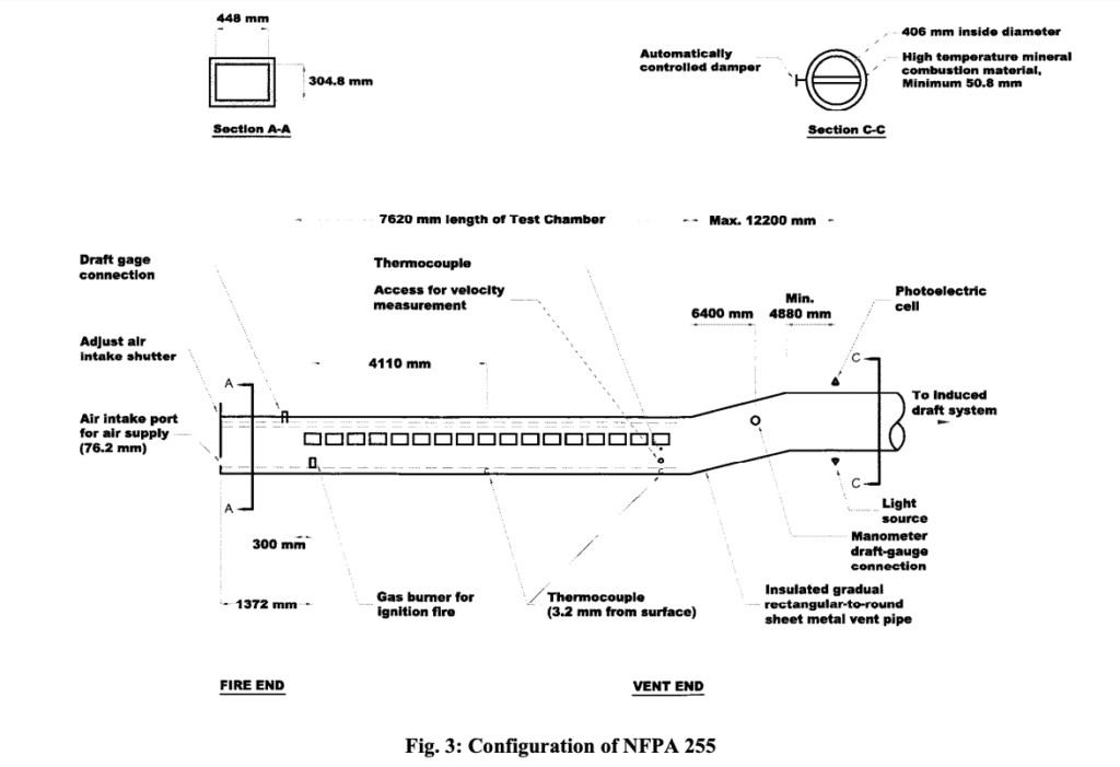
ASTM E84/NFPA 255
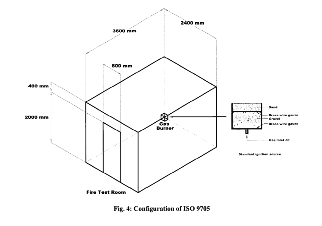
ISO 9705: 1993
| ASTM E1321 | BS476: Part 7 | ASTM E84/NFPA 255 | ISO 9705 | |
| Origins | This is an American national standard issued by the American Society for Testing and Materials (ASTM), USA, which is also referred to as the Lateral Ignition and Flame Spread Test or LIFT. The test adopted an apparatus evolved from the International Standards Organization (ISO)/International Maritime Organization (IMO) research and the scientific analysis process initiated by the Federal Aviation Administration (FAA) and carried out at the National Institute for Standards and Technology (NIST) in 1985. There are two protocols, with one for determining the ignition parameters of the materials and the other one for obtaining the lateral (opposed) low flame spread properties. | the test was developed by FOC Fire Testing Station at Borehamwood, and then introduced by the British Standards Institution (BSI). The original development of BS 476: Part 7 was initiated by some disastrous fires caused by rapid flame spread along wall linings. The test method was designed to simulate a corridor situation with a fire at one end, the radiant panel being the fire and the sample the wall lining. | This “tunnel test” was originally developed at the Underwriter’s Laboratories (UL) and adopted by the UL, National Fire Protection Association (NFPA) and the ASTM as standards, UL 723 in 1950 [14], NFPA 255 in 1955 and ASTM E84 in 1961 respectively. ASTM E84 and NFPA 255 are used by the regional and local building-code authorities in the USA. ASTM E84 has been approved by the model-building codes and NFPA 255 has been specified in the Life Safety Code (LSC) | the room/corner scenario was introduced in the 1950s in both the United States and Australia. Later, online measurement of the rate of heat release was made using the oxygen consumption method. The test for studying the reaction-to-fire properties of surface products has become an international standard, ISO 9705 since 1990 |
| Scale of tests | This standard is done by bench-scale experiments. The size of the testing sample for lateral flame spread test is 155 mm × 800 mm (0.12 m2) The specimen shall be thermally thick and tested at full thickness for materials or composites thinner than 50 mm. | The specimen should be tested at full thickness provided that it can be fitted into the specimen holder, if not, the unexposed face should be cut away to reduce the thickness to a minimum of 50 mm. For bench tests, the variations in the burning rate of products are smaller than those for full-scale tests. Further, the cost is lower as the required equipment is relatively not so expensive. Since the entire building element cannot be tested, it is always difficult to convince people that bench-scale test will give results representing the practical world. The results may differ significantly, depending on the test conditions, including temperature and heat flux. It is even established that no known bench-scale test is directly correlated with the data on flame spreading of real products. However, a basis for comparison can be provided. | ASTM E84/NFPA 255 was developed as a more realistic and comprehensive test. The results have performance similar to that observed during accidental fires for some materials and thermal exposure. A large testing specimen of exposed area 3.34 m2 (514 mm × 7.32 m) was used for allowing realistic fire involvement of material surfaces and the development of physical and structural failures that may influence the flammability performance during the testing period. The tunnel fire exposure is provided by a 1.37 m long test flame, covering 0.65 m2 of the exposed specimen surface. A moving wind-aided flame front is resulted. | is a full-scale burning test. The products are tested inside a room, 3.6m by 2.4m and 2.4m high. They can be covered on the walls (excluding that contains the doorway) and the ceiling, or just be covered on either one of them and tested with standard ceiling or wall materials. The maximum size of the testing sample is 31.7m2. This test represents a real scale fire in a small room with combustible linings. The results achieved are very close to that encountered in an actual fire. However, there might be large variations in fullscale burning rate among products, say, of the order of a factor of 100, showing a lower repeatability and reproductibility. Also, a higher cost and more preparation works arerequired for carrying out such a test. |
| Heat Source | The specimen is subjected to a gradually changing heat flux. The peak value of this flux is not a single, fixed value but is to be determined from the ignition test. The irradiance at 50 mm position from the hot end, which could be varied from 20kWm-2 to 65kWm-2 by controlling the fuel-air flow rate to the panel, is approximately 5kWm-2 higher than the minimum heat flux necessary for ignition. | Irradiance would be changed with the distance along a reference line from the inside edge of the specimen holder, i.e. 32.5 kWm-2 for 75 mm, 21 kWm-2 for 225 mm, 14.5 kWm-2 for 375 mm, 10 kWm-2 for 525 mm, 7 kWm-2 for 675 mm and 5 kWm-2 for 825 mm. The specified irradiance has a tolerance of ± 0.5 kWm-2. | The rate of heat release is about 5000 Btu/min (88 kW) on the exposure side of the tunnel. Gas temperature near the specimen surface is up to 900°C. | Two heat sources are recommended. The one more commonly used gives a thermal power of 100 kW, equivalent in intensity to a severe waste paper basket fire [30] during the first 10 min, and 300 kW for a further 10 min. The other one provides a maximum net heat output of 162 kW and gross heat output of 176 kW. The heat output shall be adjusted to 25%, 50%, 75% and 100% of the maximum net heat output at 0 s, 30 s, 60 s and 90 s after ignition respectively |
| Testing Environment | The space volume shall be bigger than 45 m3 with a ceiling height higher than 2.5 m. The apparatus shall be located with a clearance of at least 1 m separation to the walls of the room. The air supply rate shall be about 8.33 × 10⁻³ m3 s -1. The pressure and ambient temperature are controlled at about 20 to 30 Pa and 25 ± 5°C respectively. | The testing environment should be free from draughts. The test should be performed in a space with a volume bigger than 400 m3 to prevent building up of excessive heat. The minimum clearances from the radiant panel shall be 5 m in front; 1 m behind; 4 m from the floor to ceiling level; and 2.5 m on either side, measured from the panel centre. Effluent gases from the radiant panel and specimen shall be extracted without affecting the testing condition of the apparatus during the test. | The testing environmental conditions under control include air velocity (taken as the arithmetic average values at seven points along the tunnel) of 73.2 ± 1.5 m⋅min-1 and air supply at a temperature of 23 ± 2.8°C, with 50 ± 5% relative humidity. Pressure shall be maintained at the manometer reading of 9.53 mm, with no excessive air leakage. The test chamber shall be cooled down to 40.5 ± 2.8°C before putting in the new testing sample. | The testing room shall be placed in a draught free heated space which is large enough to produce no influence on the test. The temperature shall be set to 20 ± 10°C. The horizontal wind speed shall be controlled at less than 0.5 ms-1 at a horizontal distance of 1 m from the centre of the door. |
| Classification System | There is no established pass/fail criterion for the ignition and flame spread test results generated from the ASTM E1321. Indeed, the material parameters obtained can be correlated by using a simplified theory for flame spread. Hence the results can be considered suitable for use in mathematical models for fire growth and prediction of performance of materials | Travelling distances of the flame front after 1.5 min and 10 min (disregarding any flaming which occurs from the material that has slumped, melted or fallen below the position of the horizontal reference line) are measured. The results are used to classify the sample as Classes 0, and 1 to 4. At least five of the six test specimens with valid test results shall have the spread of flame (in mm) not exceeding the corresponding limits specified for the designated class as shown in Table 1 (in the standard). The remaining specimen shall not exceed this limit by more than the tolerance given. | The flame front distances at every 0.6 m or time intervals not more than 30 s are measured. The data collected are plotted against time to obtain the flame spread time-distance curve. The total area AT under the curve, ignoring any flame front recession, is used to determine the Flame Spread Index, FSI: FSI = 0.515 AT for AT ≤ 29.7 min-m (1) FSI = 4900/(195 − AT) for AT >29.7 min-m (2) Smoke generated during the tests is also compared. Smoke data collected from the photoelectric cells are plotted as a light absorption-time curve. Class A materials have an FSI of 25 or less; Class B materials have an FSI ranges from 26 to 75 while for Class C, it varies from 76 to 200. Smoke density for all the three classes should not be greater than 450. | There is no classification and product rating scheme defined officially for this test. However, by evaluating some of the critical performance aspects, a ranking system can be derived. As discussed in the literature [28], the following can be used to presume the hazards of materials. |
CONCLUSION:
The four tests on assessing the flame spreading were reviewed with the objective of introducing and comparing the concepts, scale, heat source, testing environment, flaming environment and test position, test results, and classification of materials.
Since flame spreading is a very complex phenomenon, full-scale burning tests, like ISO 9705, would give sufficient data. However, the costs of fire tests of materials, the tight budget, and fast track of design and construction of a project might not allow assessing materials with such tests. , it is possible to skillfully combine the results from the cone calorimeter with ASTM E1321 to give realistic data that would be correlated with the results from those full-scale burning tests or even real fire situations.


